Tuesday 30 August 2016

More MEMS: Dicing Challenges

30th August 2016

Back to Singapore.

Traditional Malay Style House in Geylang. Probably the last of its kind.

Colourful Shophouse 


Feeding the Hungry Ghosts

99 Red Lanterns? 


One of the big challenges in MEMS is how to  dice the wafers. Unlike conventional IC wafers:

       MEMS may contain minute and extremely delicate structures such as cantilevers, bridges, hinges, gears, membranes and other sensitive features that necessitate special handling and care.
          MEMS may contain membranes, high aspect-ratio topography and other pressure-sensitive components that cannot withstand the impact of water encountered during dicing and the subsequent cleaning cycle, and raise the need for a protective mechanism to shield them from the constant flow of liquid.
          MEMS often have moving parts that are super sensitive to contamination, and in which the presence of tiny debris particles may hinder or even halt movement altogether.
          Some MEMS (e.g. electrostatic  actuators) are highly sensitive to ESD phenomena and may fail upon spontaneous electrostatic discharges.


MEMS Dicing Challenges
From: Stealth Dicing for MEMS, Hammamatsu


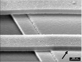
Dicing damage to MEMS membranes
 From Stealth Dicing for MEMS, Hammamatsu


Dicing Options

  1. Temporary protective layer on wafer before dicing, dice and remove protective layer
  2. Scribe and break
  3. Stealth dicing
  4. Cap before dicing

Considering each in turn:

1. Temporary protective layer
          Temporary protective sacrificial layer covers the MEMS wafer during dicing step and cleaning
          Later removed or washed away
          Usually polymer film
          Remove by dry (plasma) or wet techniques.


2. Scribe and Break

  • There are commercial systems for this eg Dynatex StreetSmart™ Breaker 
  • Applies controlled amount of stress localized to the partial saw cut one street at a time
  • As stress is applied, the remaining silicon directly below the partial saw cut breaks
Scribe and Break Schematic


3.      Stealth dicing


4 Cap before dicing
  • Individual caps or capping
  • wafer placed over the MEMS wafer
  • Caps or capping wafer can be  attached by adhesive, solder, or anodic bonding methods
  • Conventional dicing can then be applied
Cap before Dicing


Monday 22 August 2016

Jakarta and MEMS Micromachining

A few days in Jakarta, hot and sunny!

Concrete Jungle
 
Main Square in Old Jakarta

Old Jakarta
Colourful Hats and Bikes

More Colourful Hats and Bikes

Still on the subject of MEMS (Micro Electro Mechanical Systems), how is the fabrication technology different from conventional ICs (CMOS)?

The whole concept of MEMS is based on using IC technology to make micro mechanical systems but it turns out conventional IC technology is not enough. We need some additional processes.

One of the key enablers of MEMS is bulk micromachining, of which the Bosch process is most widely used.


Surface Micromachining is also widely used where we don’t need such deep structures.


Another widely used surface micromachining process is LIGA. This can be considered as an intermediate process between bulk and surface micromachining.


These three processes lie at the heart of most of the MEMS devices around us. 


Monday 15 August 2016

Greek DON'T Publish

μ
μμμμμμμμμμμμμμμμμμμμμμμμμμμμμμμμμμμμμμ

MEMS and Stiction

Back in Singapore after a few days in Kuala Lumpur


KL Skyline
Petaling Street KL

Guan Di Temple KL

Guan Di Temple KL


Singapore Skyline
from Top of Ion Orchard


A few more thoughts on reliability issues for MEMS (Micro Electro Mechanical Systems).

Stiction


Why is it such a HUGE problem?


  • Forces attracting the surfaces > forces pulling them apart (spring forces)
  • In the macro world not a big problem but in the micro world it is
  • Surface area scales with dimensions squared but volume and mass scale with dimension cubed


Elephants Don't Climb Walls
Forces that attract surfaces:
  • Capillary forces (Long range micrometres, moist environment, rough surfaces) 

  • Electrostatic forces  (Long range, micrometres, dry environment smooth or rough surfaces)
  • Hydrogen bridging  (Close range, OH terminated smooth surfaces in a dry environment)
  • Van der Waal’s forces  (Short range,  smooth surface close together in a dry environment, hydrophobic )


What can be done about it?


  • For capillary induced stiction reducing the relative humidity can help if the packaging allows it. Not always possible
  • Minimise surface contact area:
  • For bending cantilevers, try to have an arc shape rather than and "s" shape to minimise surface area of contact.


Minimise area of ContactImage based on http://www.me.unm.edu/~zleseman/news/news.htm

  • Create surface roughness or dimples on contact surfaces


Three-mask process for cantilever: 
(a) mask Idimples in oxide 
(b) mask 2, anchor in oxide

(c) structural poly deposition and mask 3, poly pattern 
(d) sacrificiaoxide layer etching
From:Introduction to Microfabrication, Sami Franssil, John Wiley, 2010
  • Coat surfaces with low surface energy materials such as diamond like carbon (DLC), Self Assembly Monolayers (SAMs) 


From:: Vapor-Phase Self-Assembled Monolayers for

Anti-Stiction Applications in MEMS, Yan Xin Zhuang et al
Journal Of Microelectromechanical Systems, 16(6), pp1451-1460, 2007

Monday 8 August 2016

A Few Thoughts about Reliability Challenges to MEMS

Had some relaxing days by the beach in Bohol after the Alabang Course last week.


Panglao

Thought I would share a few thoughts about reliability challenges to MEMS (Micro Electro Mechanical Systems) this week. In the last couple of decades MEMS have been quietly infiltrating all aspects of our lives. Where are they?

In cars:
  • Air Bag Sensors
  • Pressure sensors for engine management and tyres
  • Inertial sensors and gyroscopes for navigation
  • Anti skid braking systems
  • Headlight Levelling
  • Automatic Door Locks
  • Active Suspension


In your phone:
  • Microphone
  • Inertial and tilt sensors for screen rotation, motion sensing etc
  • Gyroscope and magnetometer for navigation
  • Autofocus actuator for camera
  • RF switches
  • Filters and oscillators
Elsewhere:
  • Infra red image sensors for security and military applications
  • Bio MEMS, Lab on a chip for health care diagnostics

and the list goes on...

From a reliability aspect, a failure in a phone may be a big inconvenience but the failure of an air bag to operate could kill someone. MEMS devices suffer from all the same challenges to reliability that most integrated circuits suffer from but because of their unique construction and applications MEMS have some extra challenges. Here are some of the main ones.

AT Blog 24/7/16 IPFA
Problem
Description
Reason for Problem
In-use stiction
Surface that should move freely get stuck together.
Capillary forces, electrostatic attraction, or chemical bonding. Influenced by surface treatment, surface contamination, and humidity
Mechanical fatigue
Repeated mechanical flexing of parts causes micro cracks which eventually  lead to failure
Conventional mechanical effects plus local oxidation
Wear
Sliding or impacting surfaces cause wear damage and debris which eventually leads to mechanical failure or sticking
Micro abrasion and cold welding. Conventional lubrication approaches usually not suitable.
Corrosion
Corrosion of metal parts due to ingress of moisture and/or ionic contaminants.
Many MEMS structures cannot be completely isolated from ambient
Electrostatic charging
Charge accumulation in dielectric layers causes hysteresis effect and possible sticking of surfaces
Charge trapping mechanisms in dielectrics
Change of shape with temperature
Bending or warping of components as temperature changes
Thermal expansion mismatch
Stress changes over life
Bending or warping of components over time caused by build up or relaxation of stress
Thin films deposited at low temperatures may anneal during operation.
E.g. electroplated Ni transforms to tensile stressed  film with annealing.


SEM picture of a capacitive RF-MEMS switch with two bridge beams, showing stiction of the front beam
From Reliability and failure analysis issues in MEMS Ingrid De Wolf (IMEC) in Microsystems Technology:  Fabrication, Test and Reliability Kogan Page Science,  2003

Wear between moving parts
From Brad Waterson , “Failure Mechanisms in Microelectromechanical Systems(MEMS)” Proc ISTFA 2002


AT Blog 24/7/16 IPFA

Tuesday 2 August 2016

Singapore and Alabang

Last week and this week I have been conducting a course on "Principles of Reliability Testing For the Semiconductor & Microelectronics Industry", two days in Singapore and two days in Alabang, part of Metro Manila in the Philippines. Was quite surprised, in the best possible way, to find that five of the course participants in Singapore were from Apple in China, four from Shenzen and one from Shanghai. In Alabang, many participants were from Maxim and Analog Devices. If you are interested in the course outline click here . Now putting final touches to "Packaging Technology & Reliability Issues For Micro- Electromechanical Systems" scheduled for 8 & 9 August in Penang and 11 & 12 August 2016 in Manila. For details click here.


With some of the course participants in Alabang
One of the topics in reliability which catches people's interest is drop impact  testing. This has become a hot topic since almost everyone now carries a sophisticated computer, camera, video-camera ,TV etc, etc around in their pocket or handbag and they expect it to work after they drop it on the floor. From the point of view of someone in electronics packaging this is most inconsiderate. In general, electronic modules don't like to be subjected to a g force of over 1000 g (Yes, that's what the phone experiences!). PCBs deform and solder joints crack. And screens crack!  You can watch an amusing YouTube video of someone abusing smart phones to destruction Click here for video (and there are plenty more!) but, sadly, the only real benefit to come from the expensive sacrifice of four innocent phones is an amusing video. Dropping phones like this, in an uncontrolled, non-reproducible. way tells us nothing about the mechanisms of failure and therefore nothing about how we can improve the reliability. One of the things we have learnt is that the g-force experienced inside the phone is strongly dependent on the orientation of the phone when it hits the ground so we need to do controlled drop testing using one of the labs set up to do this such as Halt and Hass in New Zealand. 
I like their motto "You make it, we break it"

Controlled Drop Test (From Halt & Hass Website)

There are other companies offering similar services such as:


Then you need to measure the local g-force at different locations within the phone and measure the deflection of the PCB within the phone. It turns out that the phone killer isn't the direct inertial shock on the components but flexing of the PCB damaging the solder joints. The behaviour of the PCB is quite complex:


From Drop Impact Reliability – A Comprehensive Summary, E.H. Wong et al,


Once you understand the fundamental mechanisms you can model the phones performance without any destruction at all.


Although I bet they do a few physical tests to verify the results.

Time for me to relax with a beer.