19th September 2016
Back and Forth between Malaysia and Singapore over the past couple of weeks
 |
| Petrona Towers |
 |
| KL's Colonial Heritage |
Finally sent off all my notes for the upcoming courses on
RF Package Technology : Principles,
Issues and Challenges next week
Here’s a bit of a taster on transmission lines.
There are plenty of transmission line geometries; for all except waveguide, they all have at least two conductors of which one is usually considered the ground. From an RF design perspective their most important parameter is their characteristic impedance Z0.
Waveguide is unusual in that the RF power travels inside a conducting tube, usually rectangular.
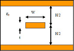
For RF Packaging we can focus on three geometries. Each of them has its "for" and "against" points
Microstrip
•Commonest Transmission Line
•Easy to fabricate
•All active components can be mounted
on top of PCB or substrate
•Microstrip
lines can couple to each other
•Microstrip
lines
can
radiate
•Microstrip
is dispersive, signals of different frequencies
travel at slightly different speeds (Not usually a problem)
Stripline
•Supports TEM Mode
•Non dispersive (But may not be true at low frequencies where resistance
of line has effect)
•Non radiating
•Excellent isolation between
adjacent traces
•Needs
transition to microstrip to connect to components on board surface
•More
complex fabrication
•Thicker
board for given impedance and trace width
•The two ground planes must be shorted
together to prevent unwanted modes. Typically use row of vias on either side. Placement of
these vias is critical
Co-planar Waveguide
•Components can be mounted on board surface
•Ground plane is on the board surface and close to signal line
•Lower dispersion than microstrip
•Popular for wideband systems eg optical telecom modules operating
over bandwidths >10 GHz
•Extremely high frequency response (100 GHz
or more) since connecting to CPW does introduce
parasitic discontinuities in the ground plane.
•Excellent Isolation between traces
•Does
NOT support TEM Mode
•Not
supported by many CAD programs
•No
simple equation for Z0


No comments:
Post a Comment